A bioreactor in biopharma is the controlled environment where cells or microorganisms grow to produce a target product, such as monoclonal antibodies, recombinant proteins, enzymes, viral vectors or other biologically derived compounds.
In practice, a bioreactor is much more than a vessel with agitation. It combines mixing, gas transfer, temperature control, process additions, sensors, data recording and operating logic to keep the culture within the conditions required by the process.
That is why selecting the right platform is not only about volume. It is about matching the process, the shear profile, the control strategy, the automation level and the intended scale, from laboratory development to pilot work and production.
What is a bioreactor?
A bioreactor is a process system designed to support and control a biological reaction. In biopharma, it is typically used upstream, where living cells or microorganisms are cultivated under defined conditions to generate biomass, metabolites or the target therapeutic product.
Depending on the process, the biological system may be mammalian cell culture, microbial culture, yeast, fungi or other production hosts. The bioreactor must then provide the right combination of mixing, oxygen transfer, nutrient addition and temperature stability while maintaining process consistency and data visibility.
The same word, bioreactor, can describe very different systems. A 2 L glass development vessel, a 50 L pilot unit and a 1000 L single-use stirred tank all solve the same process challenge at different scales, but they do not behave the same way in operation, control or plant integration.
How a bioreactor works
A stirred bioreactor works by keeping the culture environment stable while the biological system performs its function. The vessel contains the medium and the culture, agitation promotes homogeneity, gas handling supports oxygen and atmosphere control, and the automation system continuously adjusts operating conditions based on sensor feedback.
Typical functions inside the system
- Agitation to maintain mixing, suspension and heat distribution.
- Aeration and overlay control to manage oxygen transfer, carbon dioxide balance and headspace conditions.
- Temperature control through jacketed vessels or thermal support systems.
- Acid, base, antifoam or feed additions through controlled lines and pumps.
- Measurement of pH, dissolved oxygen, pressure, temperature and, in some configurations, foam, biomass or off-gas variables.
- Recipe execution, alarms, trends and data logging through the control software.
In mammalian cell culture, the operating logic usually prioritises low shear and fine control. In microbial applications, the system often needs higher oxygen transfer, higher power input and more aggressive aeration strategies.
Types of bioreactors used in biopharma
The most common format across development and manufacturing is the stirred tank reactor. Within that family, the main distinction is not only geometry, but also the process scale and whether the product path is reusable or disposable.
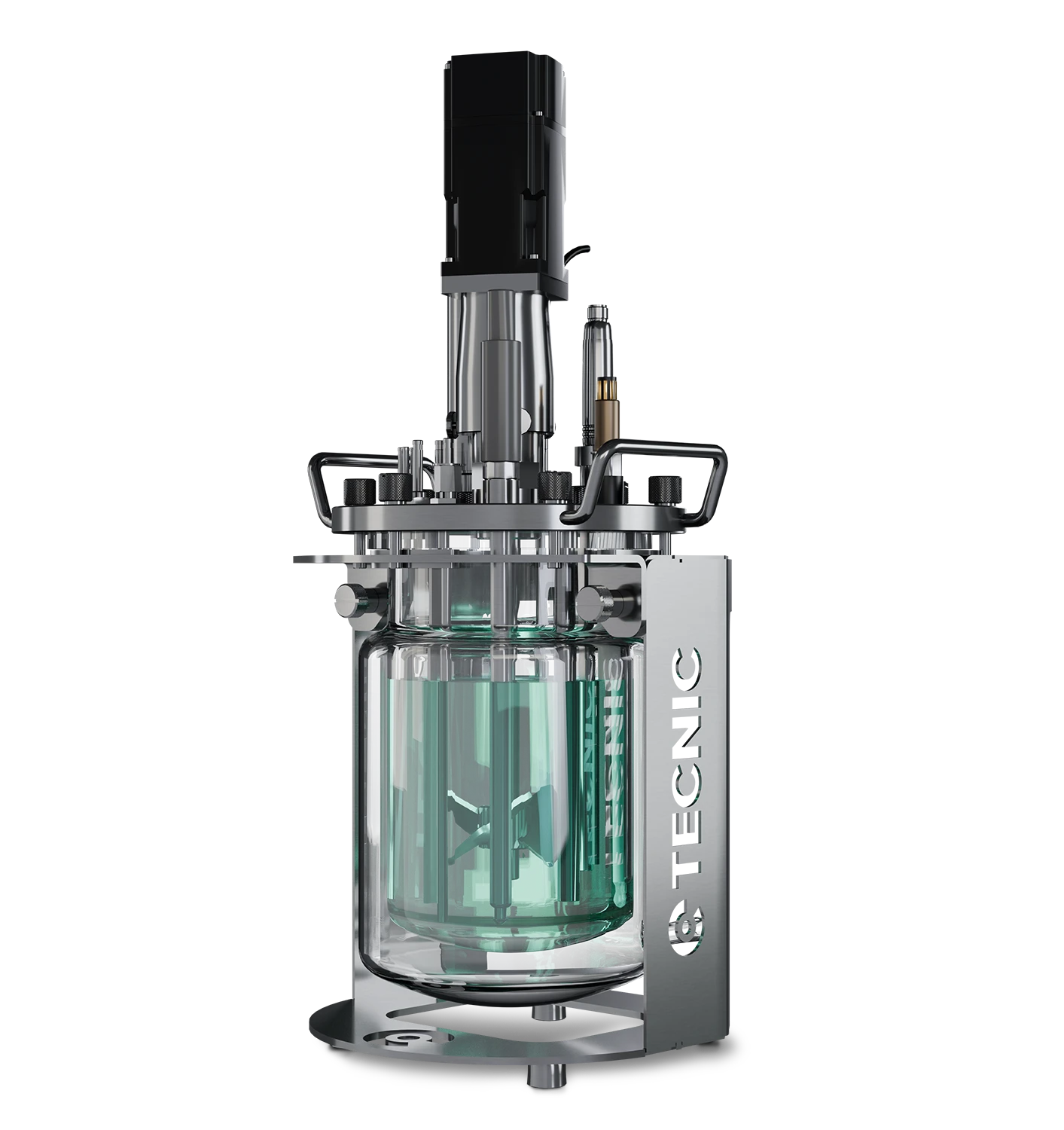
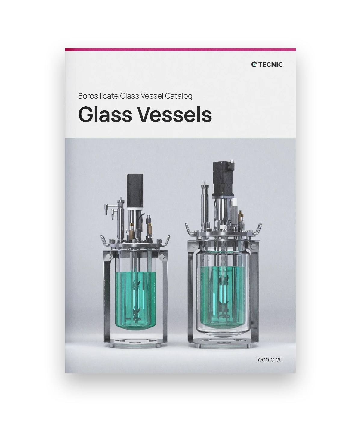
Glass vessels for laboratory work
Glass vessels remain a strong option for early-stage research, process development and scale-up studies. They offer visibility, flexibility and a practical route for labs that need controlled development work before moving into pilot or production.
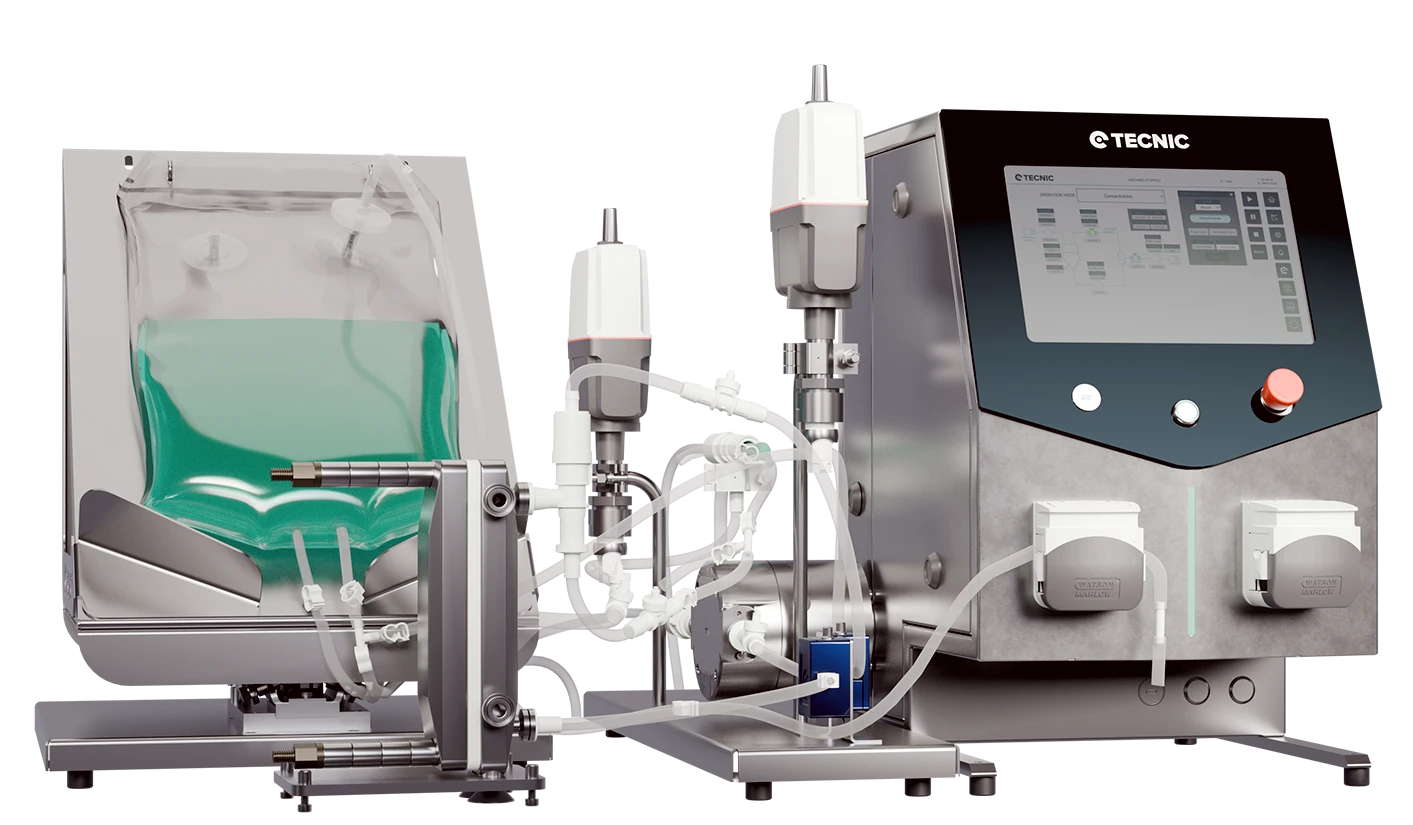
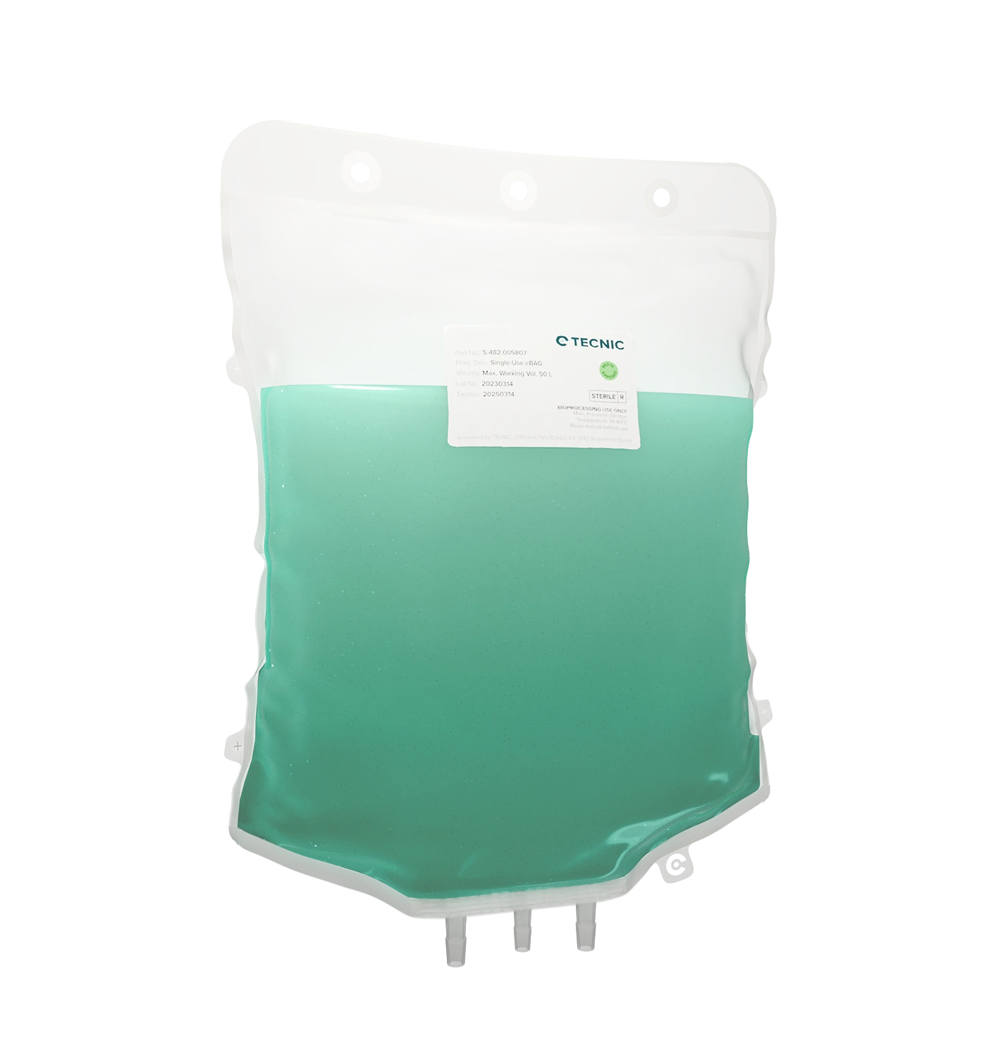
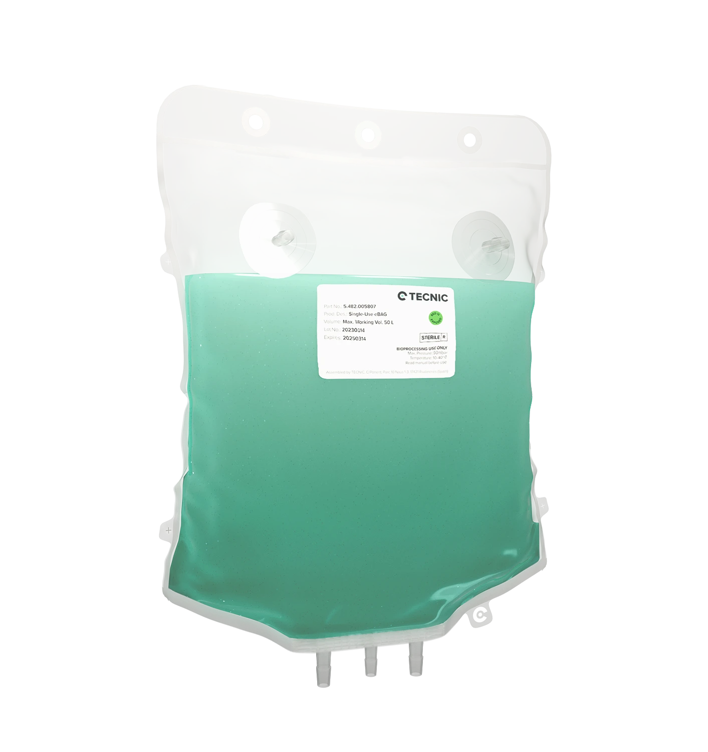
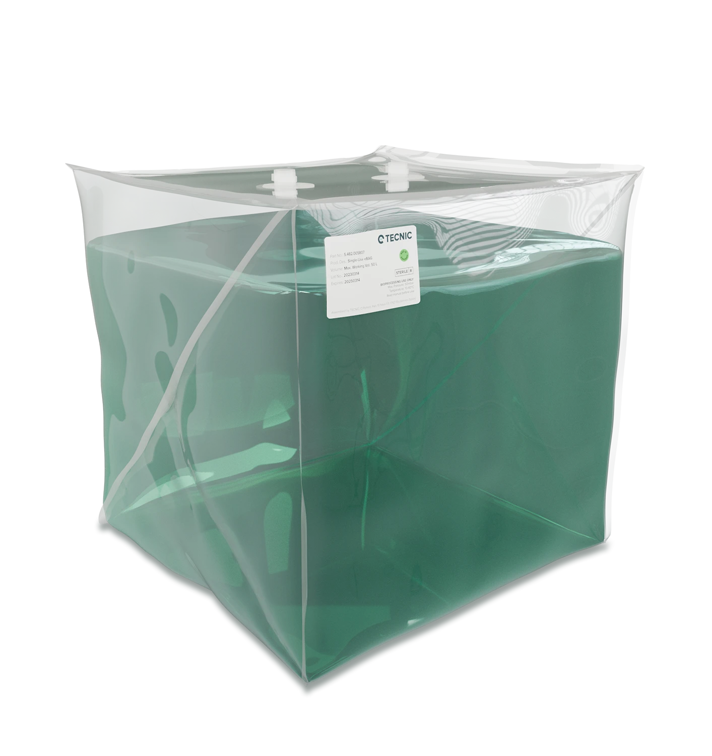
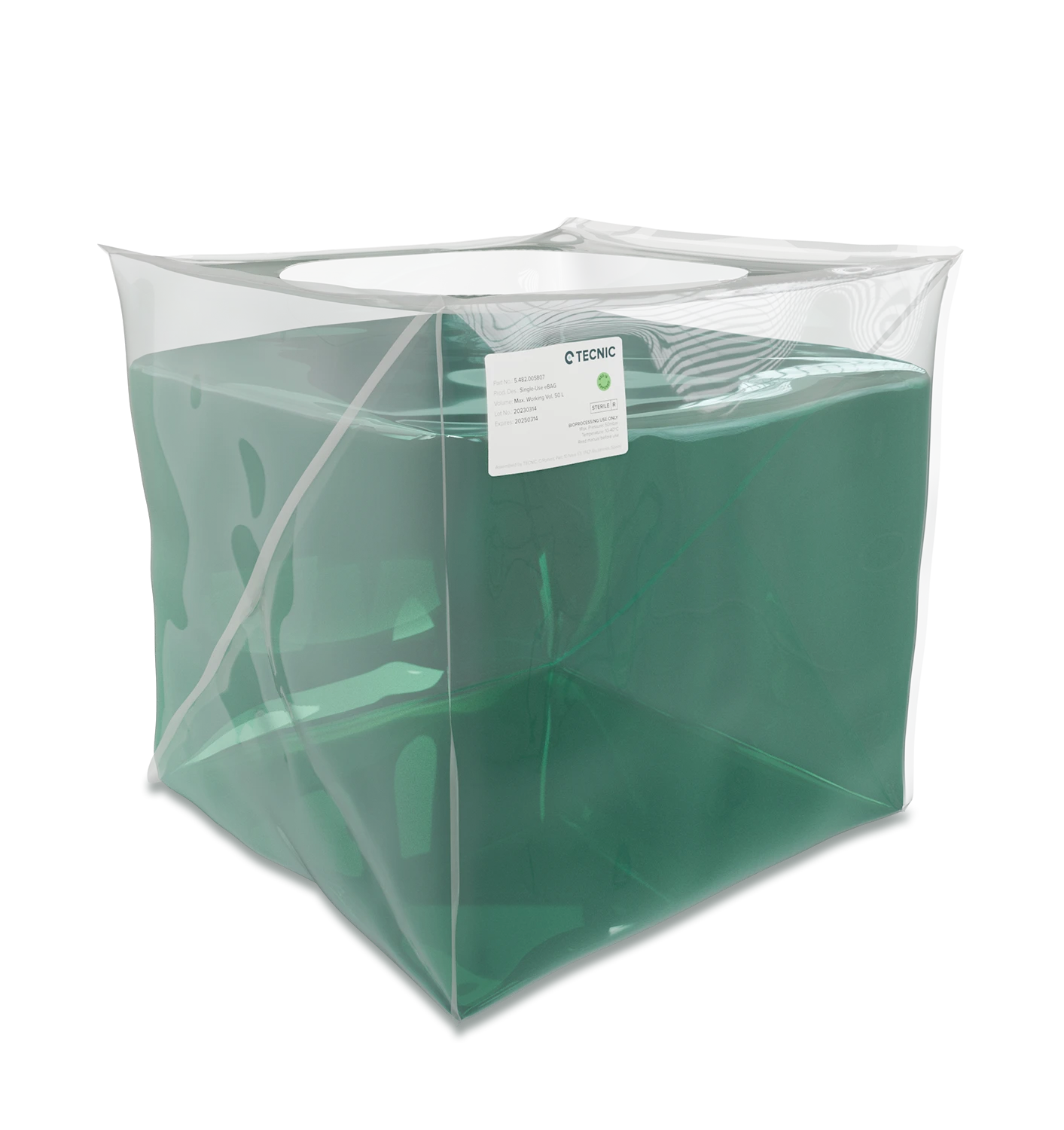
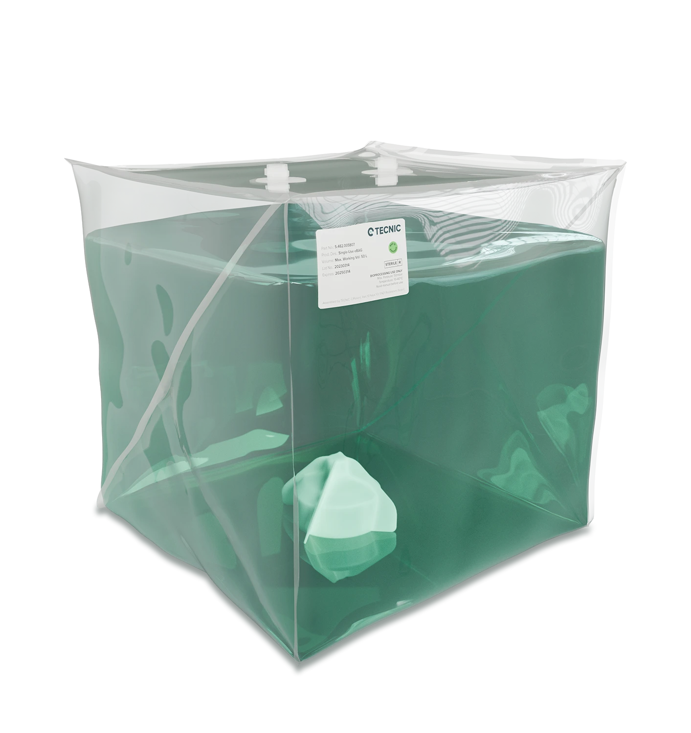
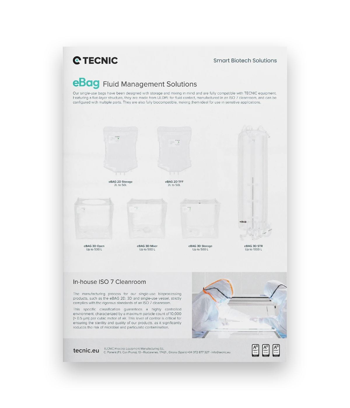
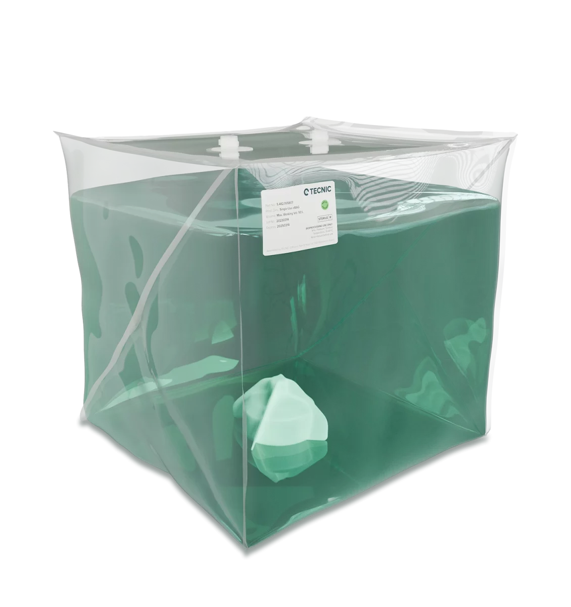
Single-use bioreactors
Single-use bioreactors are based on disposable product-contact components, typically a bag installed inside a support structure or jacketed housing. They are often selected when fast turnaround, reduced cleaning burden and operational flexibility matter.
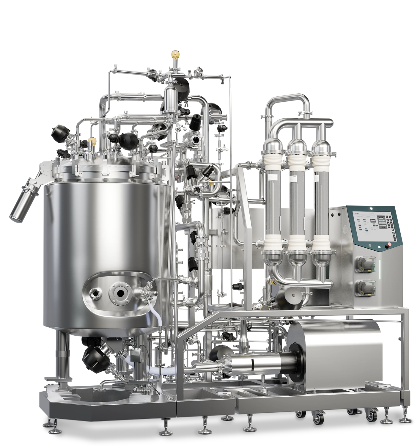
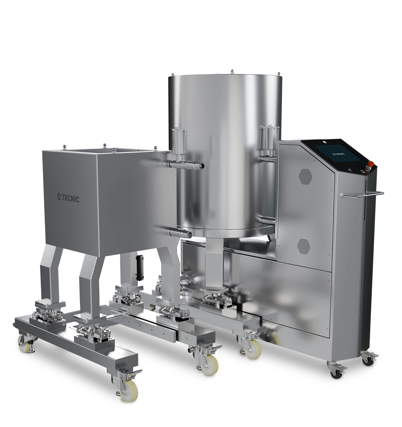
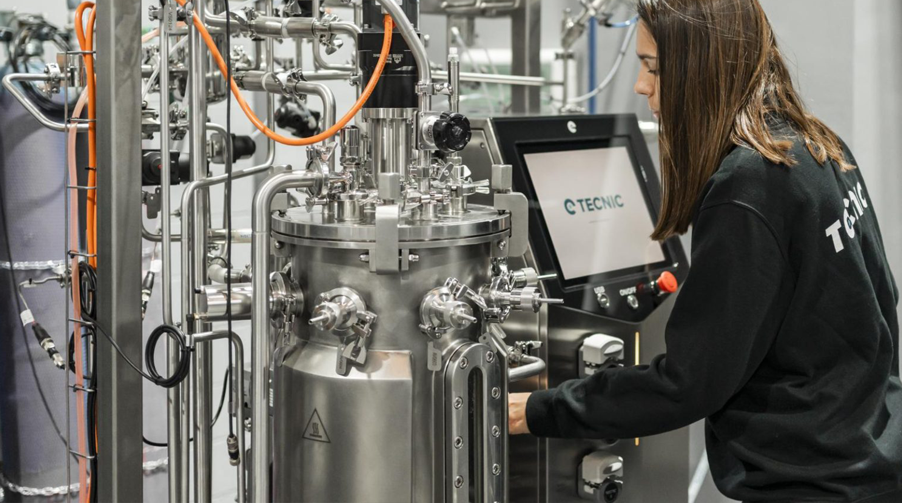
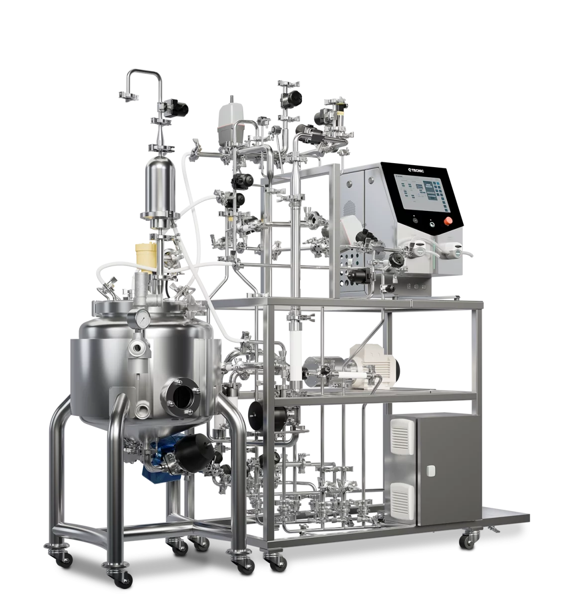
Multi-use stainless steel bioreactors
Multi-use systems remain highly relevant when the process requires robust plant integration, repeatable utilities strategy, high instrumentation density and long-term production use. They are especially common in facilities where CIP/SIP, fixed utilities and expanded validation packages are part of the operating model.
Critical process parameters in a bioreactor
A bioreactor does not perform well because it is large or highly automated. It performs well when the critical process parameters remain within the window that supports growth, productivity and product quality.
pH and dissolved oxygen
pH and DO are among the most closely watched variables because they directly influence cellular behaviour. They are usually controlled through a combination of gases, agitation and liquid additions, depending on the process strategy.
Temperature and pressure
Stable temperature protects process consistency. Pressure, where applied, can also support oxygen transfer and operating stability, but it has to remain aligned with the equipment design basis and safety philosophy.
Mixing, shear and gas transfer
These three are tightly linked. More agitation or aeration may improve transfer, but it can also raise shear. That trade-off becomes especially important when comparing mammalian cell culture against microbial processes.
The right bioreactor is not the one with the largest feature list. It is the one that can hold the process window you actually need, with enough instrumentation and control logic to scale without losing process understanding.
Single-use vs multi-use bioreactors
This is one of the most common bioreactor decisions in modern biopharma. The answer depends less on trend and more on workflow, batch strategy, facility setup and process sensitivity.
| Criterion | Single-use bioreactor | Multi-use bioreactor |
|---|---|---|
| Product-contact path | Disposable bag and associated single-use components. | Reusable stainless steel vessel and fixed process path. |
| Turnaround between batches | Usually faster, with less cleaning burden in the product path. | Depends on plant cleaning and sterilisation routines. |
| Utilities dependence | Often lower in the product-contact path, but still requires defined support systems. | Higher integration with utilities such as steam, water and fixed services. |
| Scale and plant integration | Strong where flexibility, modularity and speed matter. | Strong where long-term production and fixed plant strategy matter. |
| Operational focus | Bag handling, line management, consumables strategy and sensor setup. | CIP/SIP, mechanical hygiene, utility interfaces and fixed validation logic. |
How to choose the right bioreactor
The best starting point is not volume alone. It is the process requirement. Once that is clear, the selection becomes much more rational.
- Culture type: mammalian cell culture and microbial culture usually need different agitation and gas transfer philosophies.
- Development phase: research, process development, pilot and production do not require the same equipment architecture.
- Control needs: some projects need basic control, while others require broader integration, alarms, recipes, historian connectivity or expanded data handling.
- Operational workflow: consider cleaning strategy, consumables management, turnaround time and site utilities.
- Scale-up path: choose a platform that allows transfer logic, not just a bigger vessel.
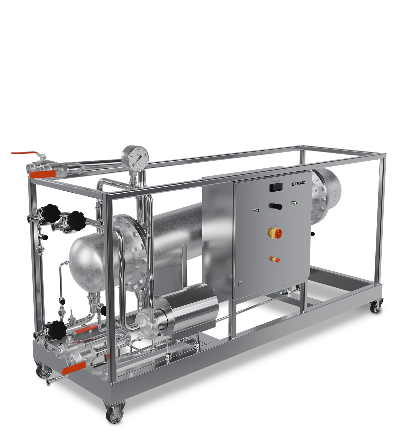
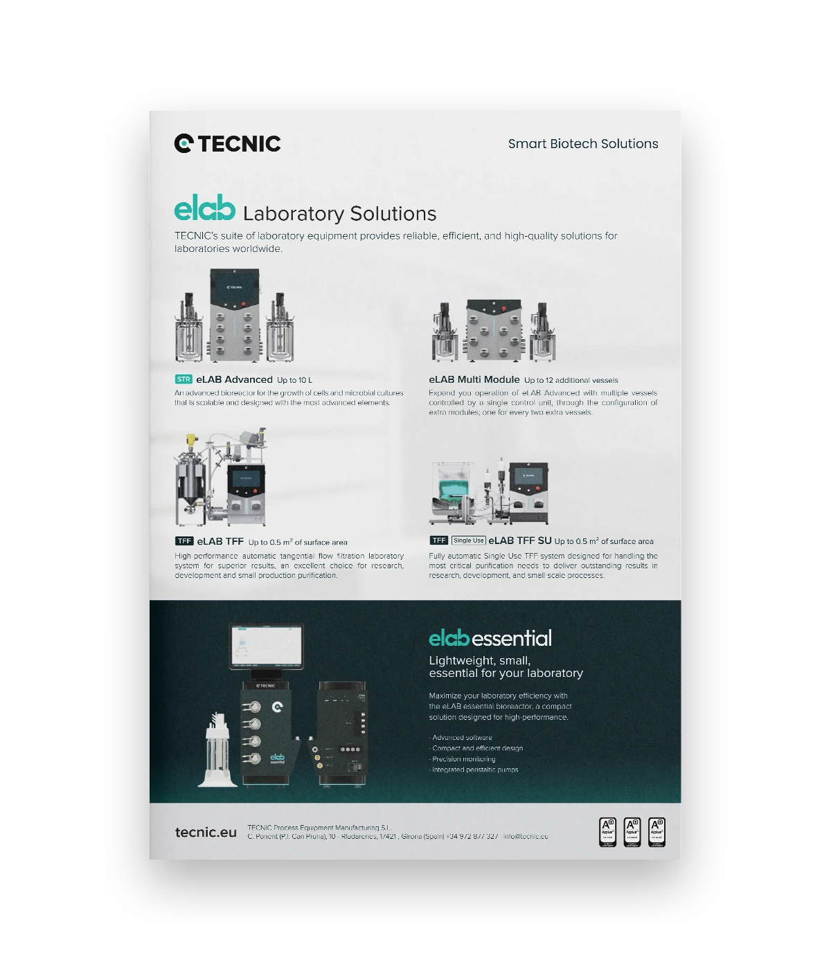
How TECNIC platforms fit this workflow
In practice, biopharma projects often move through several equipment layers rather than relying on a single system from start to finish. That is where a staged portfolio becomes useful, especially when the goal is to keep process logic aligned from laboratory work to industrial execution.
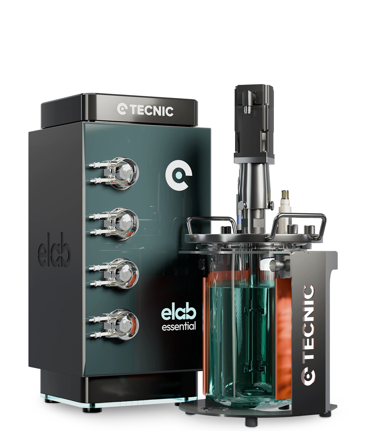
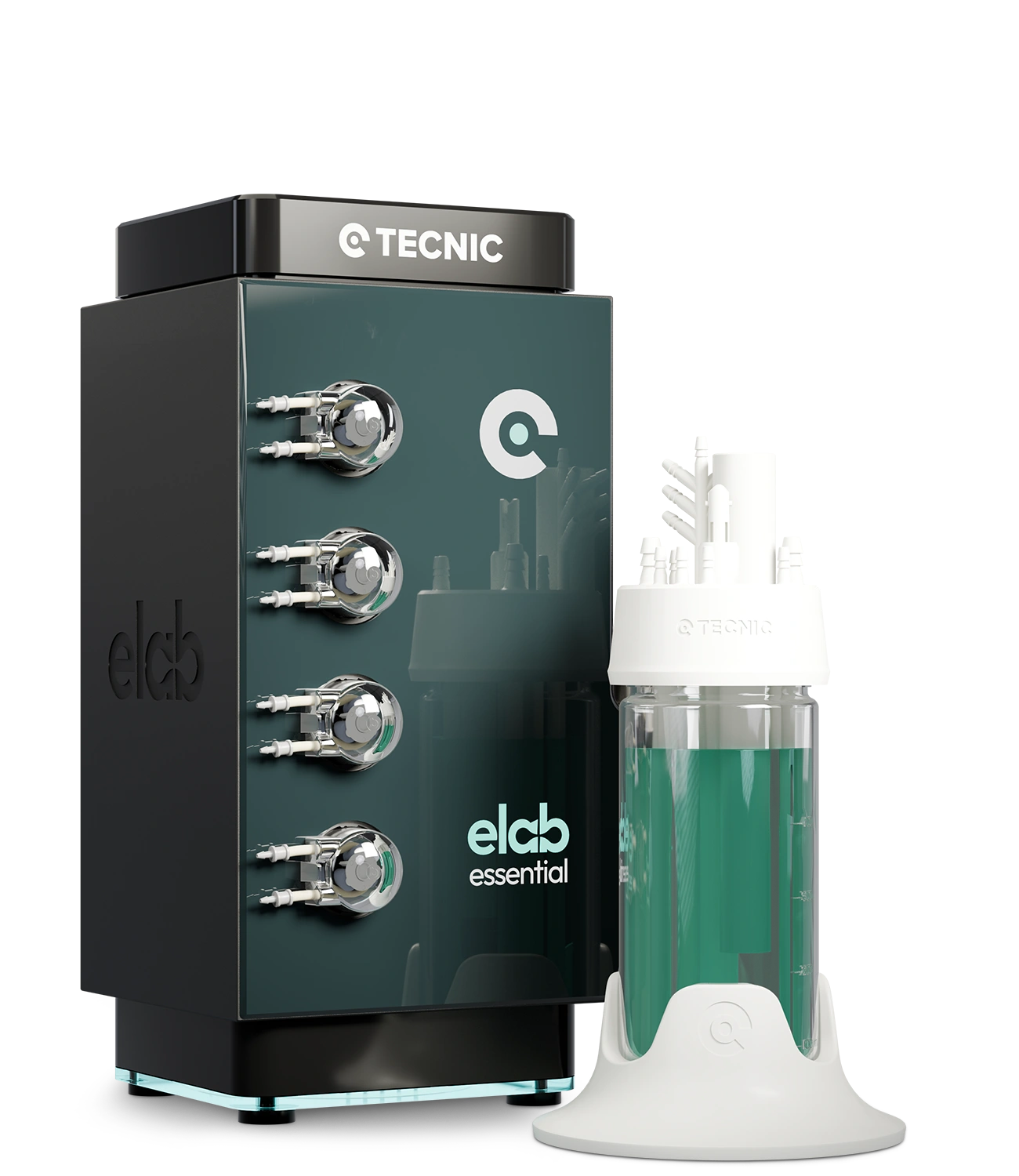
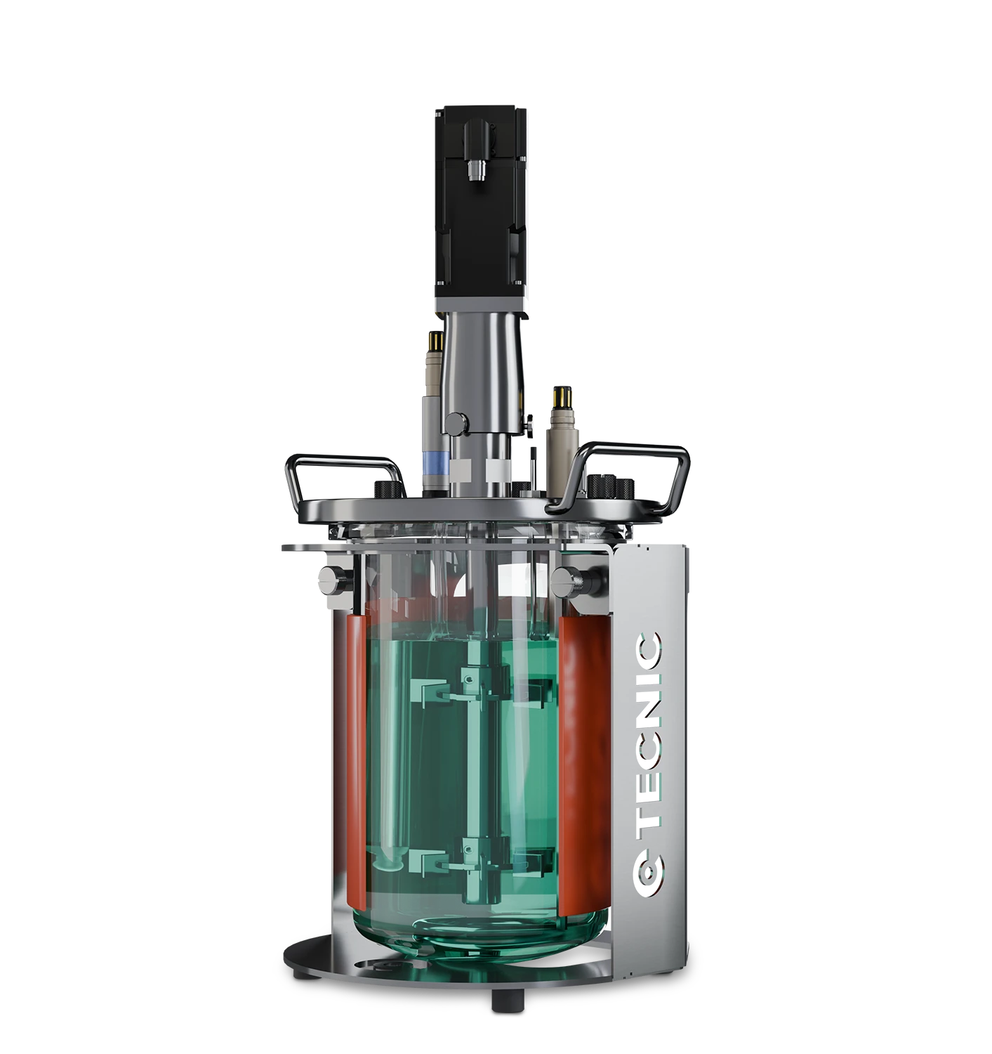
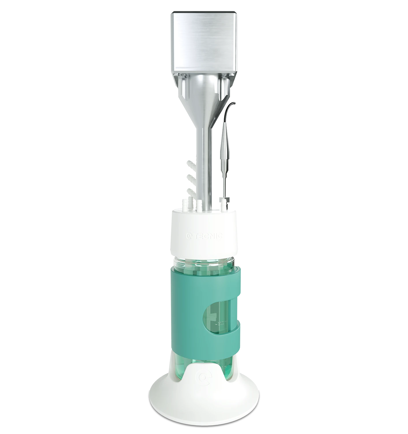
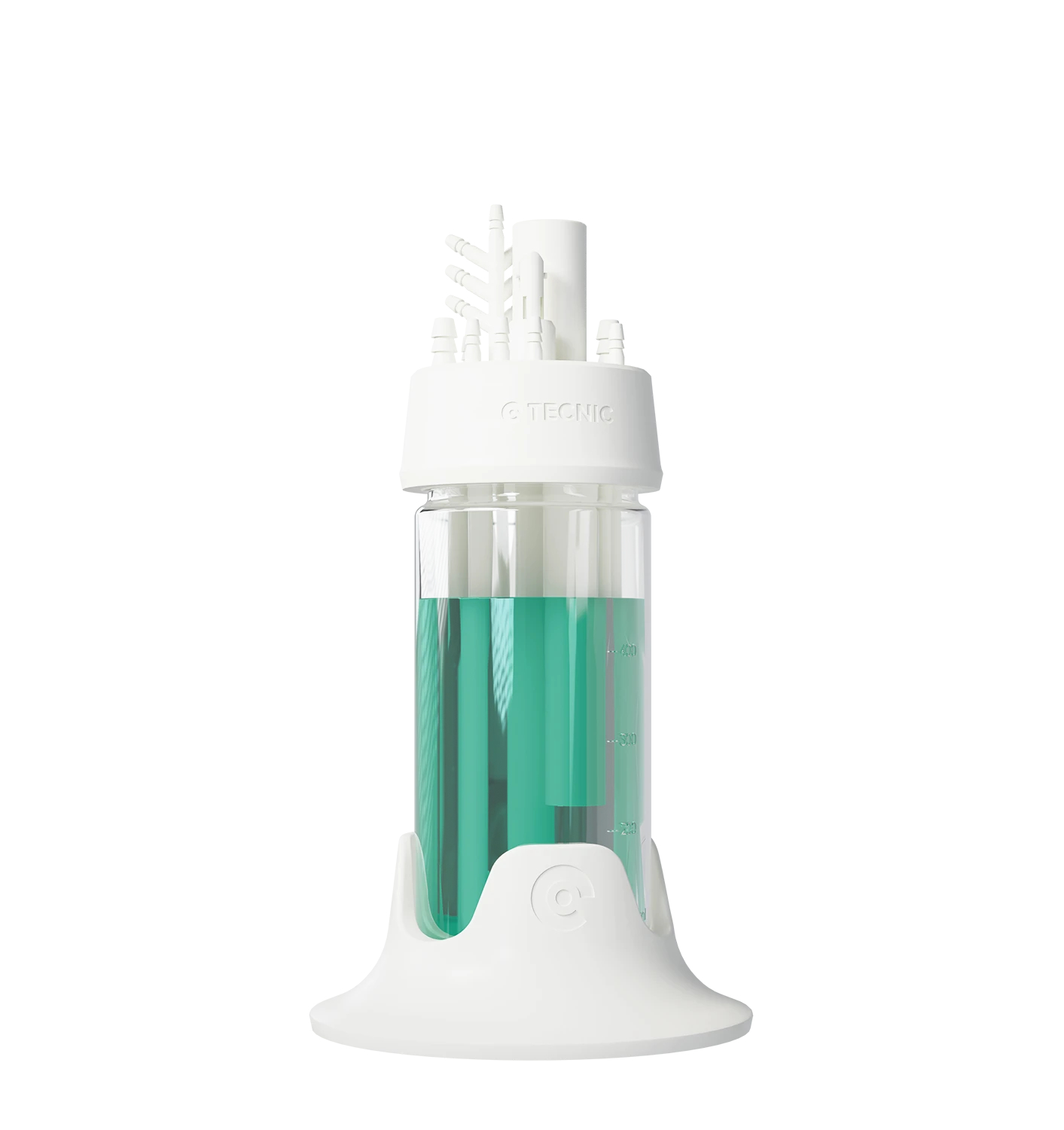
eLab Essential for laboratory development
eLab Essential is positioned for laboratory bioprocess work, supporting early development, R&D activities and scale-up studies in the lower volume range.
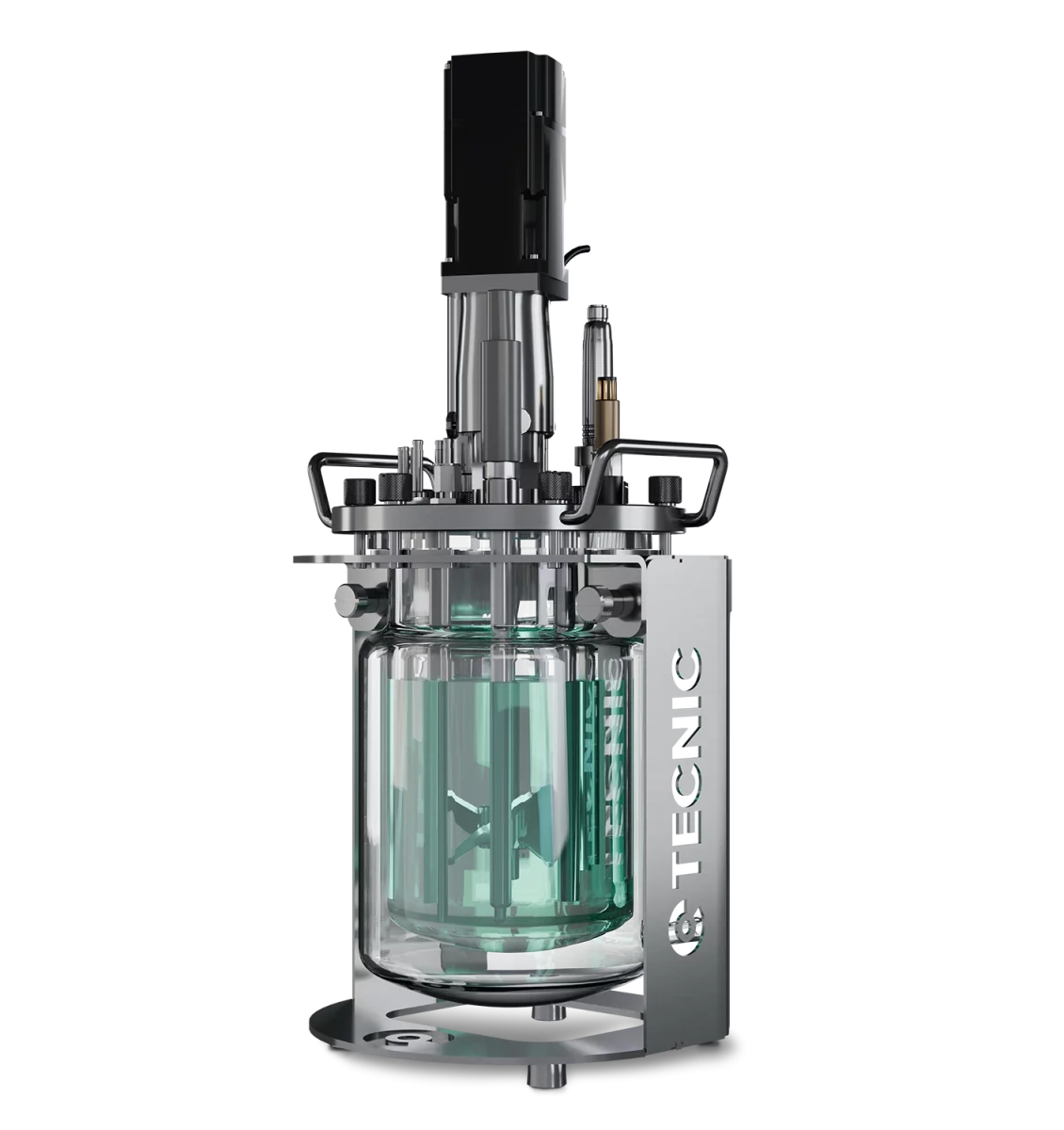
Glass Reactor for visible and flexible lab work
TECNIC also offers glass reactor formats for bioprocessing work in laboratory environments, useful where visibility, flexibility and practical development setup are important.
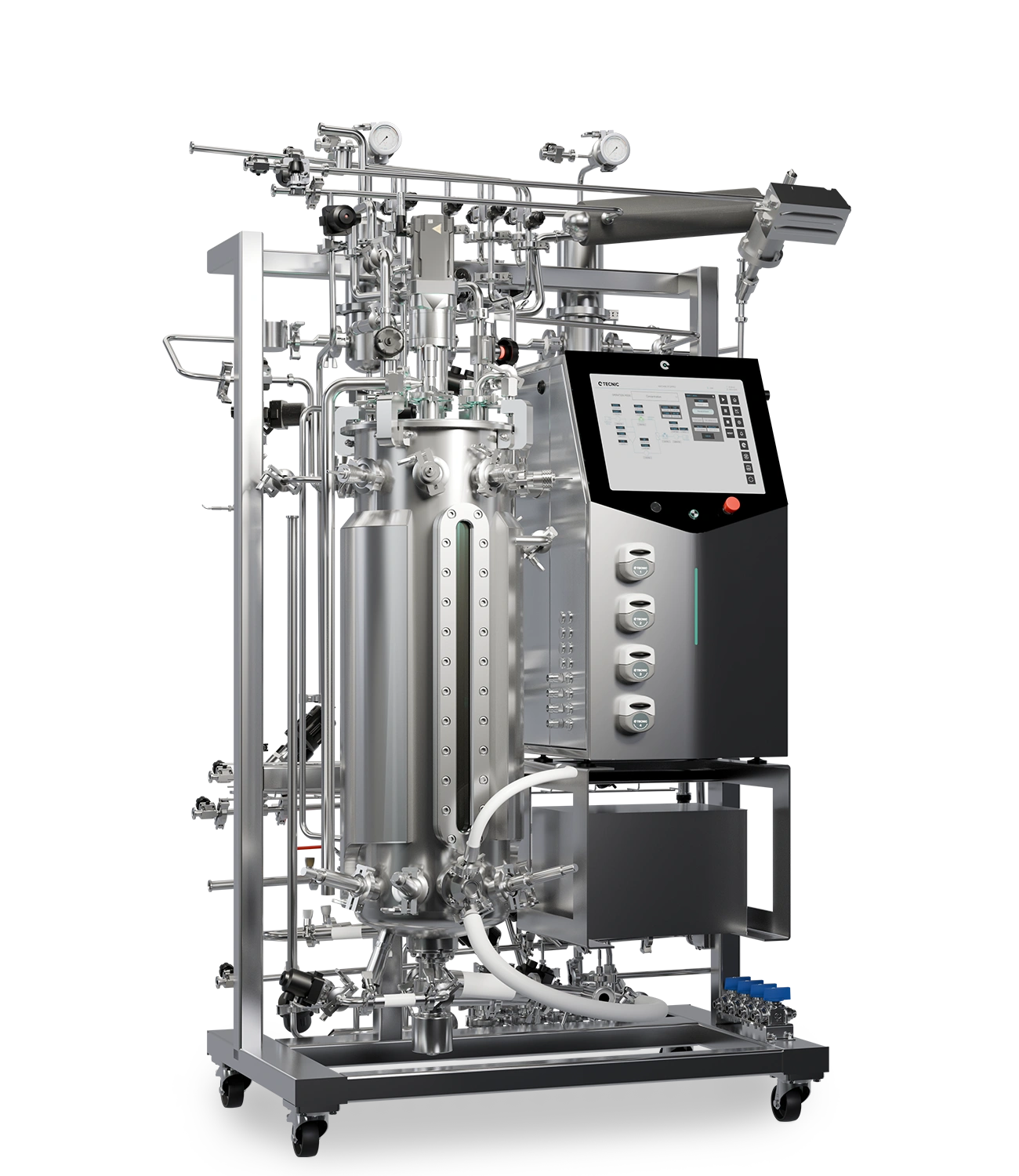
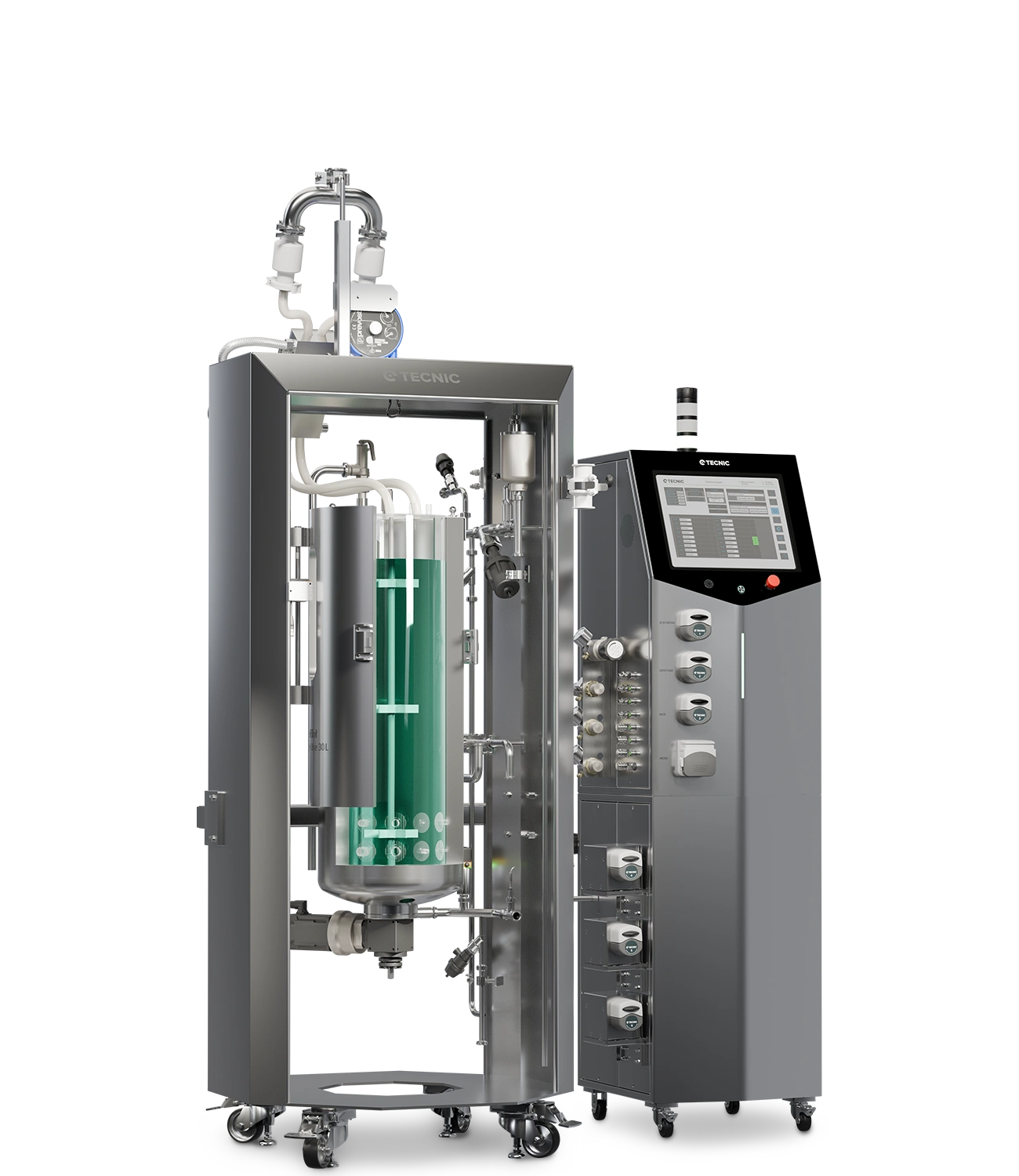
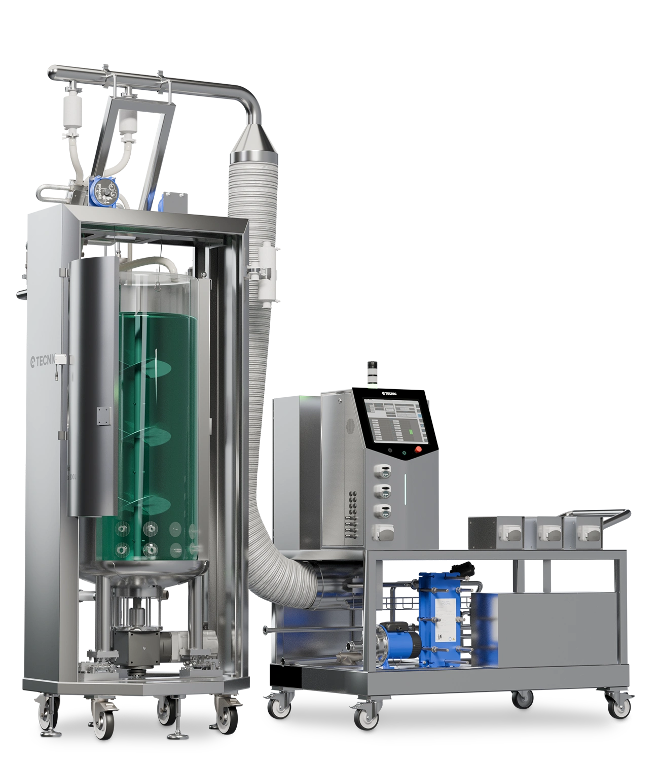
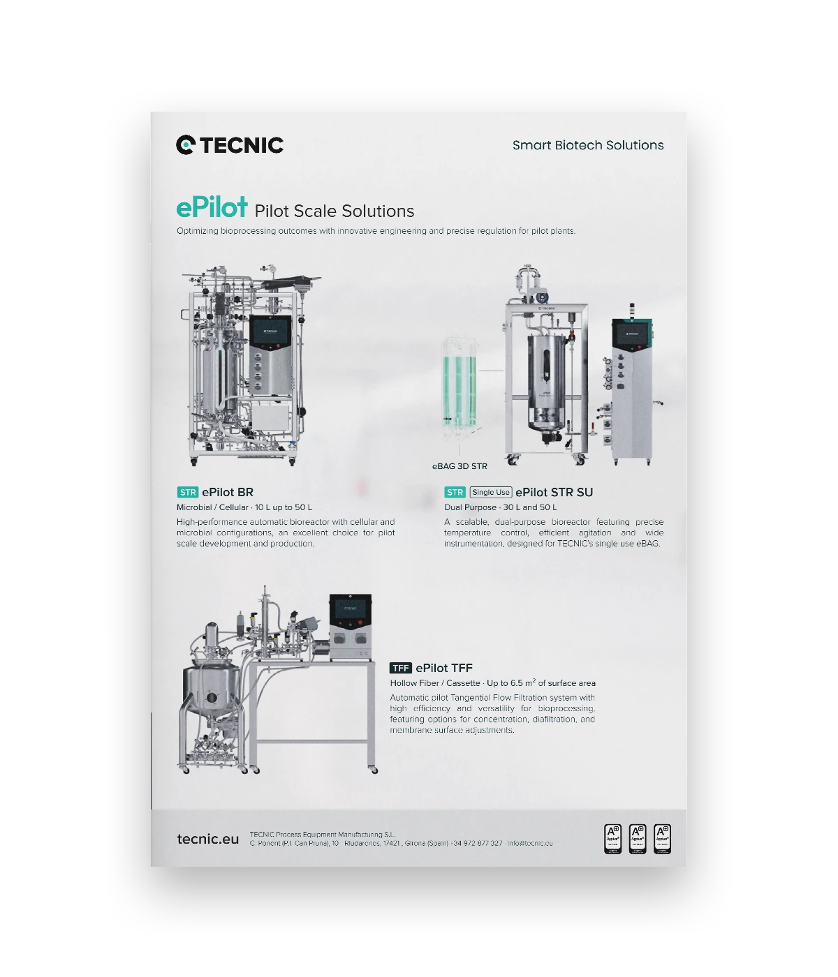
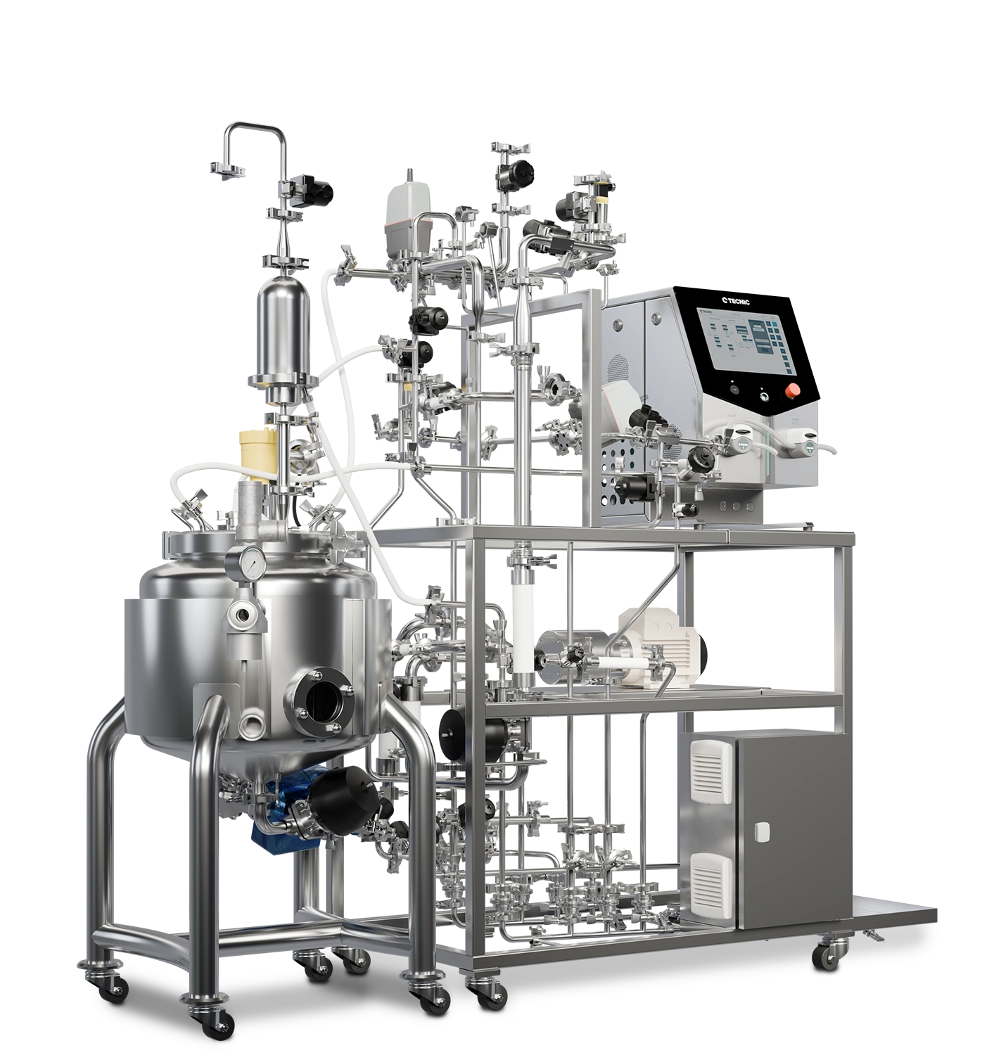
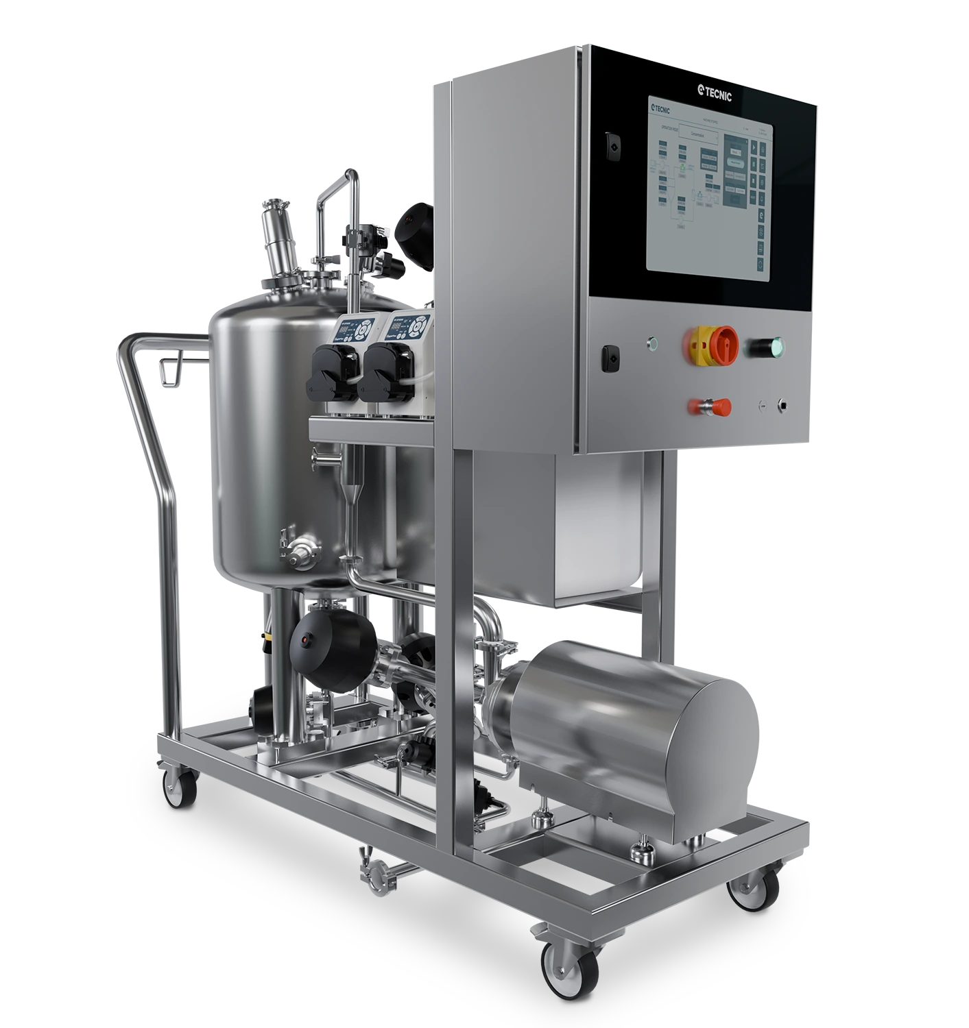
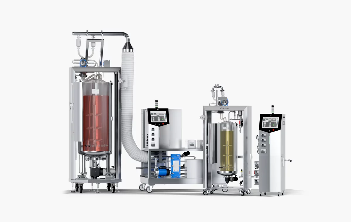
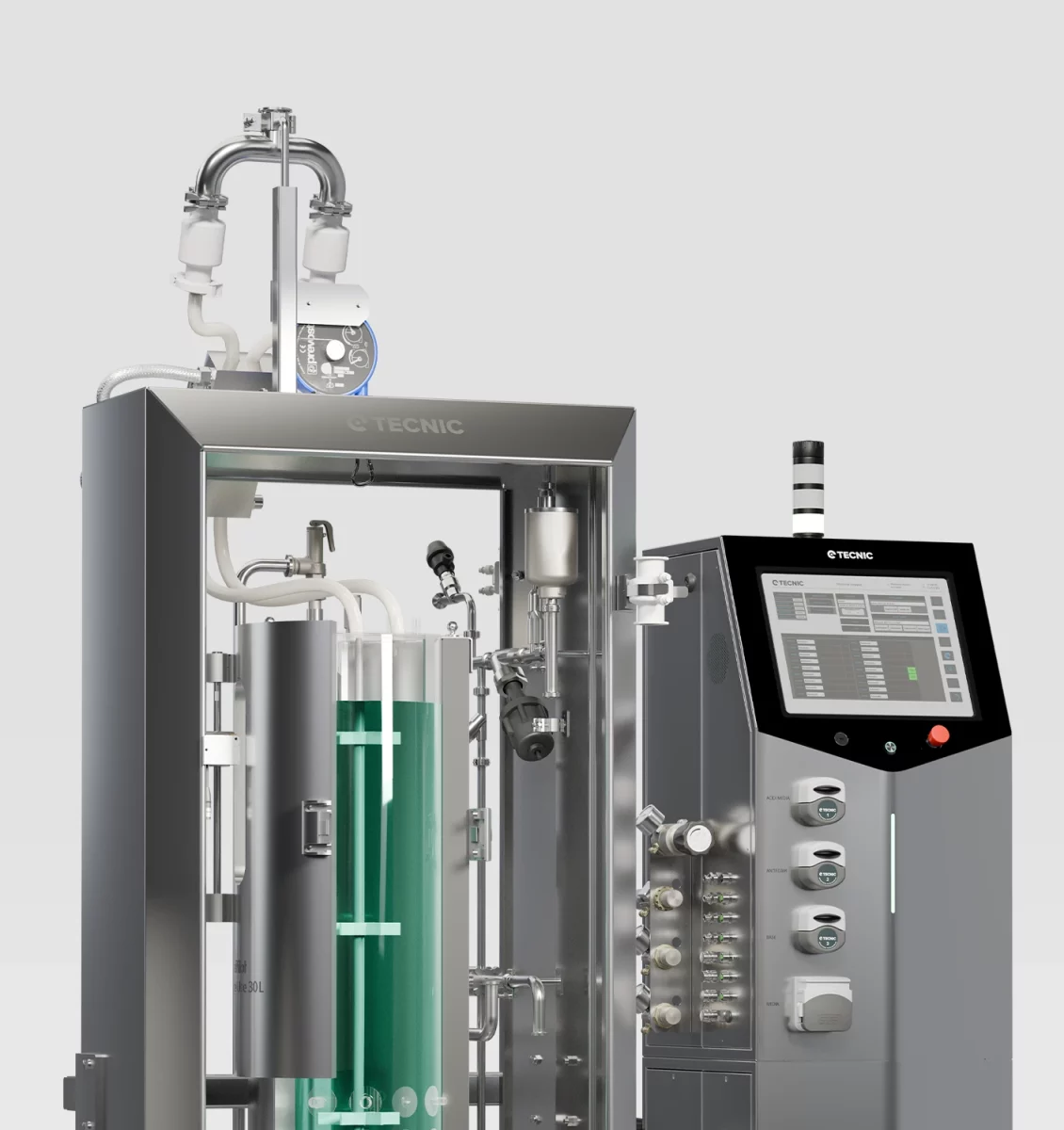
ePilot Bioreactor for pilot-scale development
ePilot Bioreactor is designed for pilot-scale process development, bridging laboratory work and larger execution with a more robust control and scale-up path.
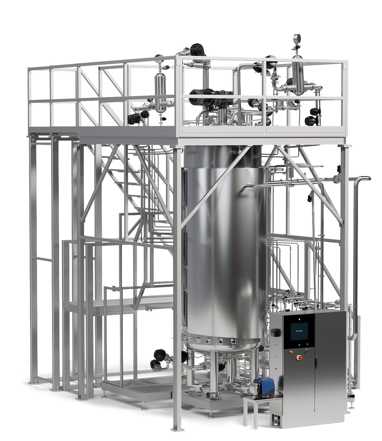
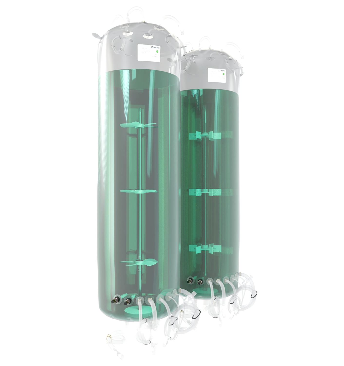
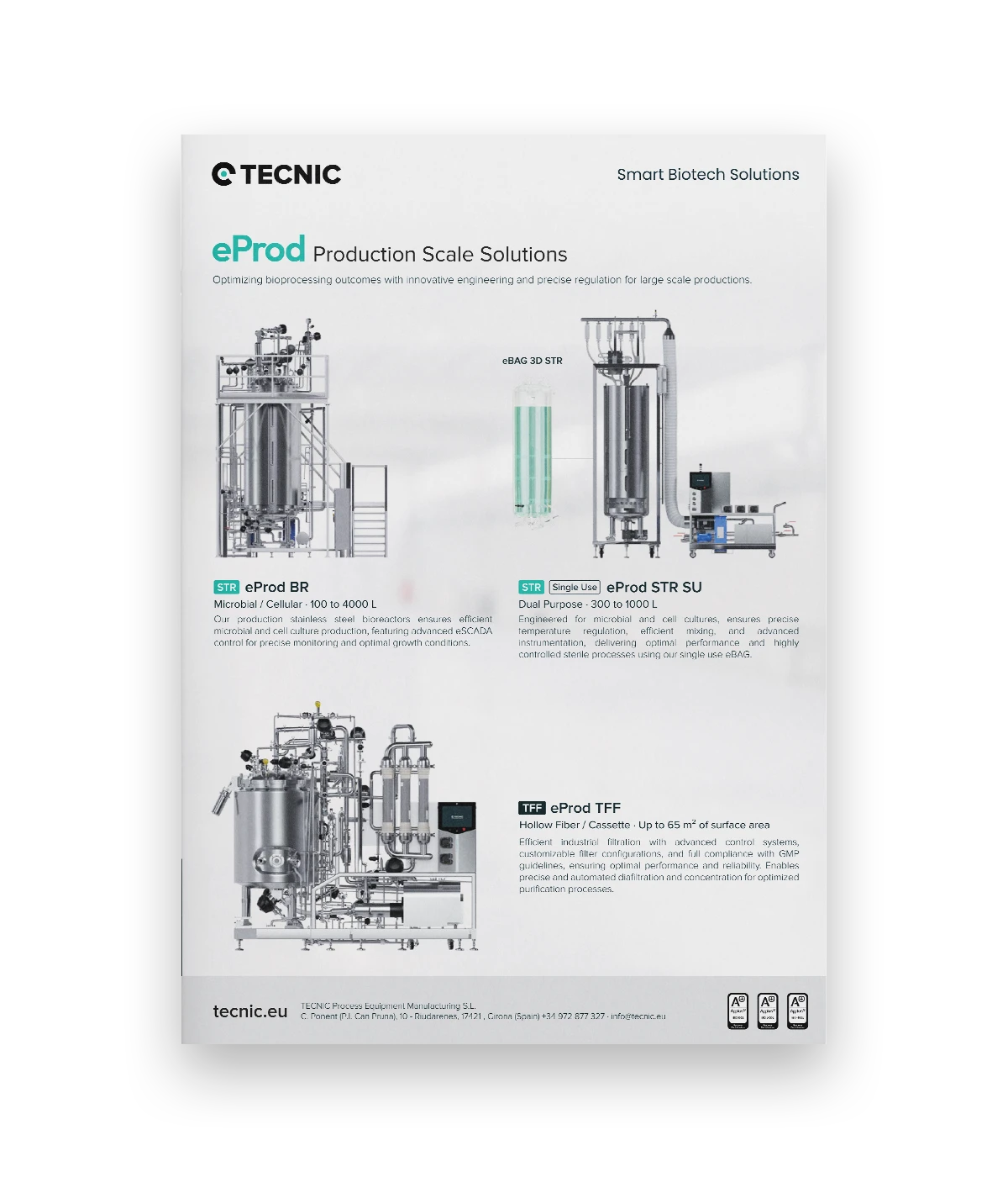
eProd Bioreactor and eProd Bioreactor SU for production
For larger-scale execution, TECNIC provides both multi-use and single-use production platforms, allowing teams to choose the operating model that best fits their process and facility strategy.
This section is intentionally technical rather than aggressively commercial. That helps the article feel natural for informational intent while still connecting the reader with real product paths.
Frequently asked questions
What is the difference between a bioreactor and a fermenter?
In practice, the terms are often used interchangeably, but fermenter is commonly associated with microbial processes, while bioreactor is broader and includes mammalian cell culture and other biological systems.
Are single-use bioreactors only for small volumes?
No. Single-use systems are widely used beyond development scale. The right question is whether the process, facility strategy and consumables model support that format efficiently.
Why are pH and dissolved oxygen so important?
Because they strongly influence growth, metabolism and productivity. Poor pH or DO control can quickly move the culture outside the intended operating window.
Can the same platform be used for cell culture and microbial processes?
Sometimes yes, but only if the agitation, gas handling, instrumentation and control philosophy match the process requirements. The differences between low-shear cell culture and high-oxygen-demand microbial work are significant.
How do I decide between lab glass vessels, pilot units and production systems?
Start with the process stage, target volume, data needs, transfer strategy and operating workflow. The right answer is usually a platform path, not a single isolated vessel decision.
Looking for the right bioreactor path from lab to production?
Explore the TECNIC bioreactor portfolio or speak with our team to review the most suitable configuration for your process, scale and control strategy.


